 In one of the earlier posts I discussed the pin out functioning of the IC 3525, using the data, I designed the following circuit which is though quite standard in its configuration, includes a low battery shut down feature and also an automatic output regulation enhancement. The following.
Feb 8, 2016 · The modified sine wave inverter is analyzed by using different PWM generating IC''s like CD4047 and SG3525 and with different designed transformer to reduce the cost and size
Get Started
pure sine wave inverter and ferrite core inverter, sg3535 dc dc converter and Spwm, low pass filter and h bridge.How to use sg3525, rectification
Get Started
Sep 20, 2013 · Dear members, I have designed push pull converter using SG3525 for pure sine wave inverter ( this is first step for it ) with specs Input Voltage = 12 V DC Output voltage = 300
Get Started
Jun 17, 2023 · In this article, we will discuss how to use the SG3525 in order to create a pure sine wave inverter circuit diagram. We will also discuss the
Get Started
Jul 13, 2021 · Looking for simple sinewave inverter circuits, which can be customized as per your specific needs? The following ideas may help you to
Get Started
Jan 16, 2022 · Sg3525 Pwm Ic Pinout Examples Applications Features Datasheet 12v Dc To 350v Symmetrical Power Supply Circuit Sg3525 Electronics
Get Started
Nov 4, 2017 · The document describes how to modify a standard SG3525 inverter circuit to produce a pure sine wave output instead of a modified square wave,
Get Started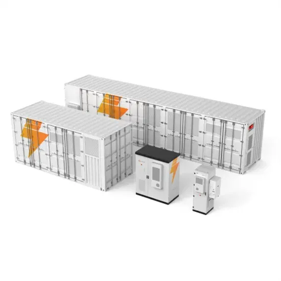
One type of inverter that produces a high-quality sine wave output is the pure sine wave inverter. The SG3525 is a popular PWM (Pulse Width Modulation)
Get Started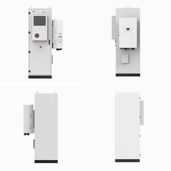
First disconnect the jumper JP1 to open the circuit loop, adjust VR1 to make the output sine wave not clipped; adjust VR2 to make the upper and lower half waves of the sine wave connect
Get Started
Nov 12, 2020 · Design Of Single Phase Sine Wave Spwm Inverter Power Supply Based On Sg3525 Electronics Engineering World Introduction To Sg3525 Is A Pulse Width Modulated
Get Started
Apr 26, 2025 · This is the most common inverter circuit based on the PWM ic of sg3525 and you will get a power output of about 500 watts will deliver. To
Get Started
Jul 8, 2014 · I Believe the SG3525 Produces Square Waves, Not Sine waves. Other than adding a Coil and Cap on the output, you won''t get Sine Wave out.
Get Started
Jun 17, 2023 · A pure sine wave inverter circuit diagram using SG3525 offers an innovative way of providing a reliable and efficient power supply for your
Get Started
Nov 25, 2019 · The SG3525 Pure Sine Wave Inverter Circuit Diagram is quickly becoming popular with both professionals and hobbyists alike. This device is
Get Started
Using SG3525 for the Basic Modified Squarewave Version We know that the IC SG3525 is designed to produce a modified sine wave output when used in an inverter topology, and
Get Started
In this article, you will learn how to design a solar inverter for home lighting and low-power applications, without the need for a microcontroller. We will be
Get Started
Apr 8, 2023 · The proposed block diagram of portable pure sine wave inverter using ferrite core transformer and double stage technique. The diagram
Get Started
Sep 2, 2023 · 12v To 220v Dc Ac Converter Inverter Circuit Diagram With Pcb Design Of Single Phase Sine Wave Spwm Inverter Power Supply Based On
Get Started
SG3525 Inverter Circuit Diagram with PWM Control and Power Stage Connections Use a symmetrical push-pull topology with the SG3525 for reliable 12V to 220V DC-AC conversion.
Get Started
Sep 7, 2017 · Design And Construction Of A Pure Sine Wave Inverter Sg3525 Inverter Driver Board 13 40khz Lm358 Adjule Dc 12 24v Driving 5000w High
Get Started
Aug 13, 2011 · I am also looking for 200 W Inverter Schematic with SG3525 ( 12 VDC to 220 vac Sine wave ) with Battery Charger with Battery Low Indication,
Get Started
From its robust PWM control to adaptive frequency response, the SG3525 remains a cornerstone in modern sine wave inverter design. As energy needs evolve, this technology continues
Get Started
Jul 29, 2019 · This document describes 3 high power sine wave inverter circuits using the SG3525 IC. The first circuit includes features for low battery
Get Started
Jul 25, 2019 · This paper designs a sine wave inverter that converts 12V DC into 220V/50Hz AC. In the DC/DC converter circuit, the push-pull circuit is used for
Get Started
Nov 30, 2022 · of 100 Watts, an o utput voltage of 22 0V, and a freque ncy of 50Hz. Keywords. Single-phase power inverter, Voltage controller, IC SG3525,
Get Started
Oct 8, 2015 · Few days ago, GoHz made a 24V 2000W power inverter in home, sharing some design schematics and circuit diagrams. Power inverter testing.
Get Started
Sep 9, 2024 · The SG3525 inverter circuit offers a versatile and efficient solution for generating both modified and pure sine wave AC outputs. It operates using a basic PWM technique to
Get Started
Apr 24, 2020 · SG3525 Applications It is used for power electronics applications like pure sine wave inverters. It is used to generate regulated voltage for dc to
Get Started
How to make a full sinusoidal inverter using the EGS002 driver board. Supplied with 12V from a battery and output 230V AC at 50Hz with SINE wave and 500W.
Get Started
Mar 22, 2020 · The circuit is based on high-frequency pulses produced by the sg3525 ic. Briefly explain the high-frequency inverter using the principle of
Get Started
Aug 1, 2014 · Sine wave inverter circuit diagram with a complete step-by-step program and coding. In this article, we will discuss how to use a push-pull
Get Started
Sep 24, 2021 · Existing inverters have square wave output sine wave output and two kinds. High efficiency of the inverter square wave output, designed for the
Get Started
The SG3525 inverter circuit offers a versatile and efficient solution for generating both modified and pure sine wave AC outputs. It operates using a basic PWM technique to regulate the output voltage, making it suitable for powering various electronic devices.
However even for an SPWM, the RMS value will need to be correctly set initially in order to produce the correct voltage output at the output of the transformer. Once implemented one can expect a real sine wave equivalent output from any SG3525 inverter design or may be from any square wave inverter model.
The sg3525 is a pulse width modulation (PWM) controller that is commonly used in inverter circuits. It generates a square wave signal that can be modified to produce a sine wave output. The inverter circuit diagram typically consists of the sg3525 controller, a power stage, and a feedback loop.
The SG3525 is a versatile PWM (Pulse Width Modulation) controller IC commonly present in inverter circuits to convert DC to AC at either 50Hz or 60Hz. Here’s a PWM based SG3525 inverter circuit with working. 1. Components Required: 2. Circuit Description:
The "chopping" is done by feeding a calculated PWM to the gates of the FET via a BJT buffer stage. A typical circuit design for converting the SG3525 waveform into a pure sine wave waveform is shown below. This design is actually an universal design which may be implemented for upgrading all square wave inverters into sine wave inverters.
The proposed SG3535 inverter circuit with output correction has been tested practically and worked well with outstanding accuracy. The prototype was tested with the below mentioned appliances: • Power. Schematic diagram of the inverter exhibits the Fig.1. Voltage 220VAC acquired by means of alternately switching windings of the transformer TS1.
 What is a sine wave inverter
 Pfc sine wave inverter price
 Sine wave 8000w 60v inverter
 Is a sine wave inverter useful
 Wind-solar hybrid sine wave inverter
 500 yuan pure sine wave inverter
 Sine wave power frequency inverter 2n3055
 Djibouti sine wave inverter manufacturer
 Port Louis pure sine wave inverter manufacturer
51 Sine Wave Inverter
Port Louis pure sine wave inverter manufacturer
51 Sine Wave Inverter
The global commercial and industrial solar energy storage battery market is experiencing unprecedented growth, with demand increasing by over 400% in the past three years. Large-scale battery storage solutions now account for approximately 45% of all new commercial solar installations worldwide. North America leads with 42% market share, driven by corporate sustainability goals and federal investment tax credits that reduce total system costs by 30-35%. Europe follows with 35% market share, where standardized industrial storage designs have cut installation timelines by 60% compared to custom solutions. Asia-Pacific represents the fastest-growing region at 50% CAGR, with manufacturing innovations reducing system prices by 20% annually. Emerging markets are adopting commercial storage for peak shaving and energy cost reduction, with typical payback periods of 3-6 years. Modern industrial installations now feature integrated systems with 50kWh to multi-megawatt capacity at costs below $500/kWh for complete energy solutions.
Technological advancements are dramatically improving solar energy storage battery performance while reducing costs for commercial applications. Next-generation battery management systems maintain optimal performance with 50% less energy loss, extending battery lifespan to 20+ years. Standardized plug-and-play designs have reduced installation costs from $1,000/kW to $550/kW since 2022. Smart integration features now allow industrial systems to operate as virtual power plants, increasing business savings by 40% through time-of-use optimization and grid services. Safety innovations including multi-stage protection and thermal management systems have reduced insurance premiums by 30% for commercial storage installations. New modular designs enable capacity expansion through simple battery additions at just $450/kWh for incremental storage. These innovations have improved ROI significantly, with commercial projects typically achieving payback in 4-7 years depending on local electricity rates and incentive programs. Recent pricing trends show standard industrial systems (50-100kWh) starting at $25,000 and premium systems (200-500kWh) from $100,000, with flexible financing options available for businesses.