 What are voltage control techniques for inverters?This is required to avoid saturation and ensure operation at constant flux density. The Voltage Control Techniques for Inverters can be affected either external to the Inverter Control or within it. The Voltage Control Techniques for Inverters can be done in two ways. (a) The variation of dc link voltage can be achieved in many ways.
Are voltage source type inverters easier to control?Voltage source type inverters are easier to control than current source type inverters. It is easier to obtain a regulated voltage than a regulated current, and voltage source type inverters can directly adjust the voltage applied to a load by varying the conduction ratio (i.e., the pulse width of a PWM signal).
What are the disadvantages of a DC link inverter?The main disadvantage of this method is that the transformer has to be designed for low frequencies and its size is large. The system also has an extremely poor dynamic response. Voltage control within the Inverter: The dc link voltage is constant and the inverter is controlled to provide-both variable voltage and variable frequency.
Can direct AC voltage control protect inverters from overcurrent?The fundamental issue with using direct AC voltage control is its inability to protect inverters against overcurrent. Thus, this paper combines AC voltage control with threshold virtual impedance. The choice of this solution is motivated by the ease of its implementation.
How do you calculate a power factor in an inverter?Generally, a power factor is represented as cosφ. θ: Electrical angle (sine-wave phase) Sine-wave signals flow through each phase of an inverter. The IGBT collector current IC is calculated as: IC = ICPx sinθ. The collector-emitter saturation voltage, VCE(sat), represents a collector-emitter voltage at the peak collector current ICP.
What is a voltage source type inverter?Voltage source type inverters control the output voltage. A large-value capacitor is placed on the input DC line of the inverter in parallel. And the inverter acts as a voltage source. The inverter output needs to have characteristics of a current source. In the case of low impedance load, series reactors are needed for each pha
What are voltage control techniques for inverters?This is required to avoid saturation and ensure operation at constant flux density. The Voltage Control Techniques for Inverters can be affected either external to the Inverter Control or within it. The Voltage Control Techniques for Inverters can be done in two ways. (a) The variation of dc link voltage can be achieved in many ways.
Are voltage source type inverters easier to control?Voltage source type inverters are easier to control than current source type inverters. It is easier to obtain a regulated voltage than a regulated current, and voltage source type inverters can directly adjust the voltage applied to a load by varying the conduction ratio (i.e., the pulse width of a PWM signal).
What are the disadvantages of a DC link inverter?The main disadvantage of this method is that the transformer has to be designed for low frequencies and its size is large. The system also has an extremely poor dynamic response. Voltage control within the Inverter: The dc link voltage is constant and the inverter is controlled to provide-both variable voltage and variable frequency.
Can direct AC voltage control protect inverters from overcurrent?The fundamental issue with using direct AC voltage control is its inability to protect inverters against overcurrent. Thus, this paper combines AC voltage control with threshold virtual impedance. The choice of this solution is motivated by the ease of its implementation.
How do you calculate a power factor in an inverter?Generally, a power factor is represented as cosφ. θ: Electrical angle (sine-wave phase) Sine-wave signals flow through each phase of an inverter. The IGBT collector current IC is calculated as: IC = ICPx sinθ. The collector-emitter saturation voltage, VCE(sat), represents a collector-emitter voltage at the peak collector current ICP.
What is a voltage source type inverter?Voltage source type inverters control the output voltage. A large-value capacitor is placed on the input DC line of the inverter in parallel. And the inverter acts as a voltage source. The inverter output needs to have characteristics of a current source. In the case of low impedance load, series reactors are needed for each pha
Dec 18, 2019 · In this paper, a direct AC voltage control-based state-feedback control is applied. Its control gains are tuned using a linear quadratic regulator. In addition, a sensitivity analysis
Get Started
Jan 3, 2025 · One of the main challenges in microgrids based on voltage source inverters is power sharing control, or in other words, balancing active and
Get Started
May 13, 2024 · Abstract—With more inverter based generations the nature of voltage variation during grid events changes requiring new approach to network voltage support. This paper
Get Started
Feb 11, 2022 · In this paper, we study the optimal structure of voltage controllers for ac inverter systems. In deriving the controller, we present a system-atic design framework for designing
Get Started
Aug 22, 2023 · Resonance Analysis of Medium Voltage Multi-Microgrids Considering the Interaction of Controllable Series Compensator and Grid-Connected Inverters | Journal of
Get Started
Jan 16, 2014 · Inverters can provide power factor and VAR support during this common occurrence to help maintain grid voltage and offset the need for installation of expensive
Get Started
The Voltage Control Techniques for Inverters can be done in two ways. by varying the dc link voltage by varying the ac voltage at the output using a variable ratio transformer (a) The
Get Started
Jan 1, 2021 · This paper is devoted to the modelling and control for a low cost, high-power quality single-phase voltage source inverter (VSI) for a grid-tied PV-based micro-inverter system. The
Get Started
Aug 17, 2018 · In this paper, we study the optimal structure of voltage controllers for ac inverter systems. In deriving the controller, we present a system-atic design framework for designing
Get Started
Aug 29, 2022 · The results clearly indicate that a controllable voltage ratio of 0.6850 and 0.6508 is achieved for the decentralized and distributed control
Get Started
Dec 23, 2020 · E-mail: zhaojinbin@shiep .cn Abstract: This study describes the design and implementation of an inverter control algorithm with both the inverter inner controllable
Get Started
Jul 2, 2021 · However, the voltage regulation techniques using smart inverters are still under research and need practical implementations. Therefore, it is essential to assess the voltage
Get Started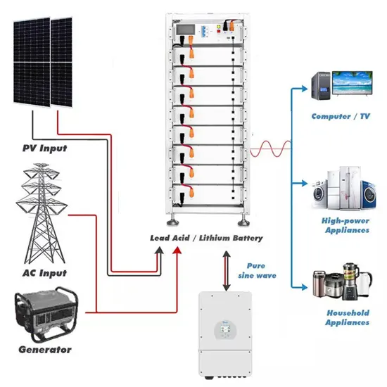
Jan 14, 2021 · Here, ''voltage ratio'' is defined as the per unit value of the desired voltage, namely the ratio between desired voltage and inverter nominal voltage. The value is entered in the text
Get Started
Jun 16, 2025 · To achieve accurate and robust voltage tracking, and to analyze the voltage controllable boundary condition, a sliding- mode control (SMC) strategy rooted in nonlinear
Get Started
On the contrary, the proposed shoot-through control scheme adjusts the shoot-through duty ratio adaptively based on load voltage feedback to improve performances. In this logic, the
Get Started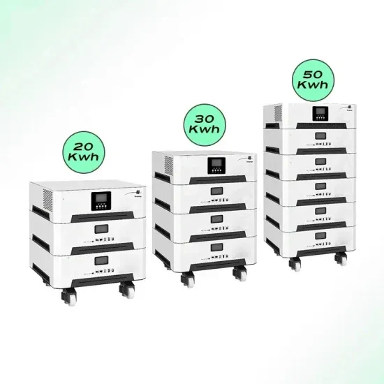
System operators typically employ distribution grid optimal power flow (DOPF) models to find the setpoints of the inverters and other legacy grid control devices. For example, DOPF is used to
Get Started
Dec 20, 2023 · Basically, if the voltage is too high and outside of the dead band, the inverter absorbs reactive power. This has the impact of reducing the
Get Started
Voltage violations are the main problem faced in distribution networks (DN) with a higher penetration of inverter-based generations (IBG). Active and reactive power control from smart
Get Started
On the contrary, the proposed shoot-through control scheme adjusts the shoot-through duty ratio adaptively based on load voltage feedback to improve performances. In this logic, the
Get Started
Nov 23, 2018 · This paper compares the inverter circuits i.e static CMOS inverter & Domino inverter with Upper & lower Self controllable Voltage Level (SVL). Power Consumption &
Get Started
Nov 17, 2020 · Entering in the over-modulation range, thus accepting a certain amount of distortion in the output voltages and input currents, it is possible to reach higher voltage
Get Started
May 15, 2025 · The RL load voltage is modified by changing firing angle α. When α < 90, Vdc is positive and when α > 90, the average dc voltage becomes negative. In such a case, the
Get Started
PDF | On May 13, 2024, Andreas Nikolaou and others published Dynamic Voltage Support of Grid-Forming Inverters | Find, read and cite all the research you need on ResearchGate
Get Started
ming inverter (GFMI) technology is capable of opera ing stably in a standalone mode and in weak grids. GFMIs are operated as controllable voltage sources. To this end, the prima y controller
Get Started
Apr 1, 2023 · This can be achieved by using a High-Frequency Inverter that involves an isolated DC-DC stage (Voltage Fed Push-Pull/Full Bridge) and the DC-AC section, which provides the
Get Started
Jul 26, 2018 · It is easier to obtain a regulated voltage than a regulated current, and voltage source type inverters can directly adjust the voltage applied to a load by varying the
Get Started
Feb 10, 2022 · Asymmetrical hybrid cascaded (AHC) multilevel inverters (MLIs) adapt in medium- and high-power applications due to their good output voltage performance and numerous
Get Started
Mar 31, 2010 · EEC 118 Lecture #4: CMOS Inverters Rajeevan Amirtharajah University of California, Davis Jeff Parkhurst Intel Corporation
Get Started
3 days ago · The output voltage of an inverter is determined by the DC input voltage and the modulation index. The modulation index represents the ratio of the inverter''s AC output
Get Started
Sep 2, 2023 · The motor exchanges its AC power with the DC power from the battery via a PWM voltage source inverter (VSI). Control outputs of voltage signals, in magnitudes, frequencies or
Get Started
Jun 14, 2024 · With the introduction of the controllable power electronic switch, induction motor drives have transitioned away from the grid and moved to the voltage source inverter (VSI).
Get Started
Jul 4, 2021 · The paper describes a current inverter scheme, based on fully controllable switches with a low modulation frequency of the output curve. There are two ways to r
Get Started
Dec 7, 2012 · Permanent-magnet synchronous motors (PMSM) are capable of providing high torque-to-current ratios, high power-to-weight ratios, high efficiency and robustness. Owing to
Get Started
A matrix converter is defined as a converter with a single stage of conversion. It utilizes bidirectional controlled switch to achieve automatic conversion of power from AC to AC. It
Get Started
Aug 11, 2021 · Three Phase PFC Topology - Vienna topology The Vienna topology is a controllable active power rectifier. Controllable output voltage and BUS balance
Get Started
The conventional quasi z-source inverters (QZSIs) are not capable of producing DC-side voltage gain through duty ratio control of switching pulses during non-shoot-through operation.
Get Started
This is required to avoid saturation and ensure operation at constant flux density. The Voltage Control Techniques for Inverters can be affected either external to the Inverter Control or within it. The Voltage Control Techniques for Inverters can be done in two ways. (a) The variation of dc link voltage can be achieved in many ways.
Voltage source type inverters are easier to control than current source type inverters. It is easier to obtain a regulated voltage than a regulated current, and voltage source type inverters can directly adjust the voltage applied to a load by varying the conduction ratio (i.e., the pulse width of a PWM signal).
The main disadvantage of this method is that the transformer has to be designed for low frequencies and its size is large. The system also has an extremely poor dynamic response. Voltage control within the Inverter: The dc link voltage is constant and the inverter is controlled to provide-both variable voltage and variable frequency.
The fundamental issue with using direct AC voltage control is its inability to protect inverters against overcurrent. Thus, this paper combines AC voltage control with threshold virtual impedance. The choice of this solution is motivated by the ease of its implementation.
Generally, a power factor is represented as cosφ. θ: Electrical angle (sine-wave phase) Sine-wave signals flow through each phase of an inverter. The IGBT collector current IC is calculated as: IC = ICPx sinθ. The collector-emitter saturation voltage, VCE(sat), represents a collector-emitter voltage at the peak collector current ICP.
Voltage source type inverters control the output voltage. A large-value capacitor is placed on the input DC line of the inverter in parallel. And the inverter acts as a voltage source. The inverter output needs to have characteristics of a current source. In the case of low impedance load, series reactors are needed for each phase.
 High voltage inverter ultra high voltage
 Inverter converts DC high voltage pulse
 Inverter output voltage series capacitor
 The output voltage of an inverter worth tens of dollars
Can the inverter high voltage capacitor be charged
The output voltage of an inverter worth tens of dollars
Can the inverter high voltage capacitor be charged
 320v voltage inverter
 Sunshine PV inverter DC voltage
 Adjustable inverter output voltage
 50kw inverter rated voltage
 Can high voltage electricity be connected to an inverter
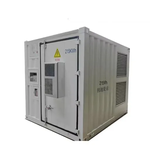
The global commercial and industrial solar energy storage battery market is experiencing unprecedented growth, with demand increasing by over 400% in the past three years. Large-scale battery storage solutions now account for approximately 45% of all new commercial solar installations worldwide. North America leads with 42% market share, driven by corporate sustainability goals and federal investment tax credits that reduce total system costs by 30-35%. Europe follows with 35% market share, where standardized industrial storage designs have cut installation timelines by 60% compared to custom solutions. Asia-Pacific represents the fastest-growing region at 50% CAGR, with manufacturing innovations reducing system prices by 20% annually. Emerging markets are adopting commercial storage for peak shaving and energy cost reduction, with typical payback periods of 3-6 years. Modern industrial installations now feature integrated systems with 50kWh to multi-megawatt capacity at costs below $500/kWh for complete energy solutions.
Technological advancements are dramatically improving solar energy storage battery performance while reducing costs for commercial applications. Next-generation battery management systems maintain optimal performance with 50% less energy loss, extending battery lifespan to 20+ years. Standardized plug-and-play designs have reduced installation costs from $1,000/kW to $550/kW since 2022. Smart integration features now allow industrial systems to operate as virtual power plants, increasing business savings by 40% through time-of-use optimization and grid services. Safety innovations including multi-stage protection and thermal management systems have reduced insurance premiums by 30% for commercial storage installations. New modular designs enable capacity expansion through simple battery additions at just $450/kWh for incremental storage. These innovations have improved ROI significantly, with commercial projects typically achieving payback in 4-7 years depending on local electricity rates and incentive programs. Recent pricing trends show standard industrial systems (50-100kWh) starting at $25,000 and premium systems (200-500kWh) from $100,000, with flexible financing options available for businesses.