 What is the difference between a voltage comparator and a non inverting comparator?Fig1 shows a voltage comparator in inverting mode and Fig shows a voltage comparator in non inverting mode. Non inverting comparator. In non inverting comparator the reference voltage is applied to the inverting input and the voltage to be compared is applied to the non inverting input.
How does a non inverting comparator work?Non inverting comparator. In non inverting comparator the reference voltage is applied to the inverting input and the voltage to be compared is applied to the non inverting input. Whenever the voltage to be compared (Vin) goes above the reference voltage , the output of the opamp swings to positive saturation (V+) and vice versa.
What is a voltage comparator based on opamp?Voltage comparator circuit. Voltage comparator is a circuit which compares two voltages and switches the output to either high or low state depending upon which voltage is higher. A voltage comparator based on opamp is shown here. Fig1 shows a voltage comparator in inverting mode and Fig shows a voltage comparator in non inverting mode.
Do CMOS inverter-based comparators have threshold voltage control?This paper proposes a novel solution for CMOS inverter-based comparators with threshold voltage control. The solution was simulated in a 28-nm bulk technology u.
What is the inverting configuration of op-amp comparator?The following figure shows the inverting configuration of comparator. The input signal is applied at inverting terminal of op-amp. The reference voltage Vref = 0V. Due to open loop configuration of op-amp, the output goes into saturation. 1. If Vin>Vref then Vo= – Vsat.
Can a reference voltage be changed externally?The reference voltage can be changed externally with the help of potential divider arrangement. This reference voltage can be either positive or negative as shown in circuit diagram below. If the supply voltage is positive, the reference voltage is also positive. If the supply voltage is negative, the reference voltage is also negati
What is the difference between a voltage comparator and a non inverting comparator?Fig1 shows a voltage comparator in inverting mode and Fig shows a voltage comparator in non inverting mode. Non inverting comparator. In non inverting comparator the reference voltage is applied to the inverting input and the voltage to be compared is applied to the non inverting input.
How does a non inverting comparator work?Non inverting comparator. In non inverting comparator the reference voltage is applied to the inverting input and the voltage to be compared is applied to the non inverting input. Whenever the voltage to be compared (Vin) goes above the reference voltage , the output of the opamp swings to positive saturation (V+) and vice versa.
What is a voltage comparator based on opamp?Voltage comparator circuit. Voltage comparator is a circuit which compares two voltages and switches the output to either high or low state depending upon which voltage is higher. A voltage comparator based on opamp is shown here. Fig1 shows a voltage comparator in inverting mode and Fig shows a voltage comparator in non inverting mode.
Do CMOS inverter-based comparators have threshold voltage control?This paper proposes a novel solution for CMOS inverter-based comparators with threshold voltage control. The solution was simulated in a 28-nm bulk technology u.
What is the inverting configuration of op-amp comparator?The following figure shows the inverting configuration of comparator. The input signal is applied at inverting terminal of op-amp. The reference voltage Vref = 0V. Due to open loop configuration of op-amp, the output goes into saturation. 1. If Vin>Vref then Vo= – Vsat.
Can a reference voltage be changed externally?The reference voltage can be changed externally with the help of potential divider arrangement. This reference voltage can be either positive or negative as shown in circuit diagram below. If the supply voltage is positive, the reference voltage is also positive. If the supply voltage is negative, the reference voltage is also negati
Aug 28, 2018 · What is a Comparator? The comparator is a circuit that compares one analog signal with another analog signal or a reference voltage and outputs a binary signal based on
Get Started
Oct 29, 2020 · A voltage comparator is a circuit which compares the voltages at its input terminals and switches the output to either high or low depending
Get Started
Jun 4, 2024 · I''m confused about the offset of the comparator. Consider a comparator consisting of a pre-amp and an inverter. Does the offset come
Get Started
Oct 5, 2021 · Abstract This paper presents an energy-efficient comparator with a novel dynamic pre-amplifier (pre-amp). By using an inverter-based input pair powered by a floating reservoir
Get Started
Jan 10, 2016 · Also, based on theoretical analyses, a new dynamic comparator with low-voltage low-power capability was proposed in order to improve the performance of the comparator.
Get Started
Operational amplifiers are well described in many publications and a lot of information can be found regarding the design and proper use of these devices. On the other hand, information
Get Started
Jun 15, 2022 · This paper proposes a novel solution for CMOS inverter-based comparators with threshold voltage control. The solution was simulated in a 28-nm bulk technology under 0.5-V
Get Started
4 days ago · In the first way, shown in Figure 1, we connect the comparator inverter input to a pair of resistors whose values will determine the reference
Get Started
Aug 18, 2025 · Op amp, and comparator integrator circuits (ICs), are always comparing the voltages at the inverting input and the non inverting input.
Get Started
Jun 25, 2012 · It just so happens I have 3 unused CD4069 inverters in there, as well... Just for the sake of elegance & streamlining, is it possible to coax an inverter ("tweak" its threshold level
Get Started
Aug 28, 2018 · Example 33-2 – Optimizing the Propagation Time Delay A comparator consists of an amplifier cascaded with a latch as shown below. The amplifier has a voltage gain of 10V/V
Get Started
This paper presents a novel self-tuning inverter-comparator for a pulse width modulator. The inherent threshold voltage of the inverter-comparator is made indep
Get Started
Apr 11, 2022 · A voltage comparator (also known as a comparator) is a very common integrated circuit. It can be utilized in V/F conversion circuits, A/D
Get Started
Apr 7, 2021 · The comparator is an instrument that used to compares the input voltage Vin (t) to reference voltage and on and off the transistor according to
Get Started
Jun 4, 2025 · This paper presents the design of a high-precision, low-voltage inverter-based comparator. The comparator employs current-limiting and current calibration circuits to reduce
Get Started
The invention relates to an inverter based comparator with variable switching point inverters and a completely digital Flash ADC design using variable switching point inverter based comparator
Get Started
Feb 23, 2019 · Explanation of difference between Opamp and comparator chips. Tutorial to help you choose Opamp vs comparator to use in your circuit design.
Get Started
Jun 16, 2025 · What is a comparator ? A comparator is an electronic circuit that compares the voltage levels of two input signals and produces a binary output
Get Started
This paper introduces a single-ended non-offset-cancelled flash ADC architecture, the "Threshold Inverter Quantizer" (TIQ). The TIQ is based on a CMOS
Get Started
Mar 7, 2025 · eme for voltage comparison using Inverter based comparator is shown in Fig. 1. In the figure, VIN is the input signal, kVLSB is the reference voltage of the kth comparator and
Get Started
May 8, 2025 · Many users who focus on inverters may consider using them as comparators. However, in reality, inverters cannot function as comparators because the voltage levels in
Get Started
This paper introduces a single-ended non-offset-cancelled flash ADC architecture, the "Threshold Inverter Quantizer" (TIQ). The TIQ is based on a CMOS inverter cell, in which the voltage
Get Started
Mar 6, 2025 · My question is, what intended purpose would the opamp/comparator serve for a half-bridge inverter circuit? Is this designed to
Get Started
May 10, 2019 · A comparator is normally used in applications where some varying signal level is compared to a fixed level (usually a voltage reference). Since it is, in effect, a 1-bit analog-to
Get Started
4 days ago · A voltage comparator is more than an operational amplifier that has a very high gain and can operate normally with a simple power supply. We
Get Started
A comparator is an electronic circuit, which compares the two inputs that are applied to it and produces an output. The output value of the comparator indicates which of the inputs is
Get Started
Dec 29, 2021 · This is not what is required. Instead of a single falling edge Output signal, there are now four falling edges on the example shown. Consider a
Get Started
Fig1 shows a voltage comparator in inverting mode and Fig shows a voltage comparator in non inverting mode. Non inverting comparator. In non inverting comparator the reference voltage is applied to the inverting input and the voltage to be compared is applied to the non inverting input.
Non inverting comparator. In non inverting comparator the reference voltage is applied to the inverting input and the voltage to be compared is applied to the non inverting input. Whenever the voltage to be compared (Vin) goes above the reference voltage , the output of the opamp swings to positive saturation (V+) and vice versa.
Voltage comparator circuit. Voltage comparator is a circuit which compares two voltages and switches the output to either high or low state depending upon which voltage is higher. A voltage comparator based on opamp is shown here. Fig1 shows a voltage comparator in inverting mode and Fig shows a voltage comparator in non inverting mode.
This paper proposes a novel solution for CMOS inverter-based comparators with threshold voltage control. The solution was simulated in a 28-nm bulk technology u
The following figure shows the inverting configuration of comparator. The input signal is applied at inverting terminal of op-amp. The reference voltage Vref = 0V. Due to open loop configuration of op-amp, the output goes into saturation. 1. If Vin>Vref then Vo= – Vsat
The reference voltage can be changed externally with the help of potential divider arrangement. This reference voltage can be either positive or negative as shown in circuit diagram below. If the supply voltage is positive, the reference voltage is also positive. If the supply voltage is negative, the reference voltage is also negative.
 Power inverter input voltage
 Can high voltage electricity be connected to an inverter
 50kw inverter rated voltage
 High voltage inverter ultra high voltage
 15kv high voltage inverter
 Sunshine PV inverter DC voltage
 High voltage 100 000 volt inverter
 12v24v inverter maximum withstand voltage
 Photovoltaic inverter voltage source
 Adjust the inverter voltage
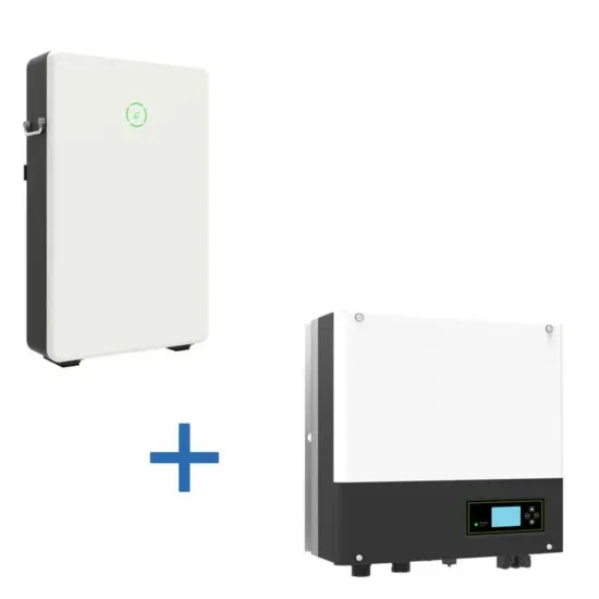
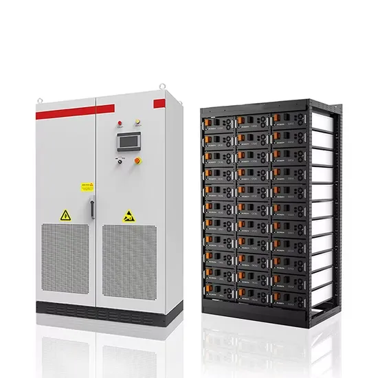
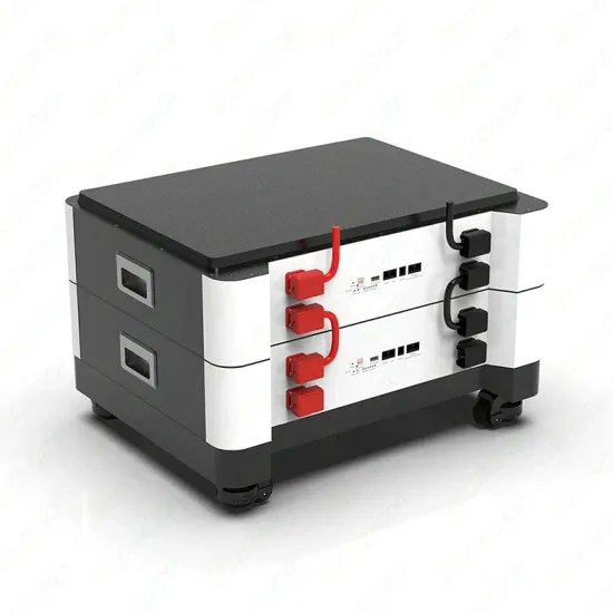
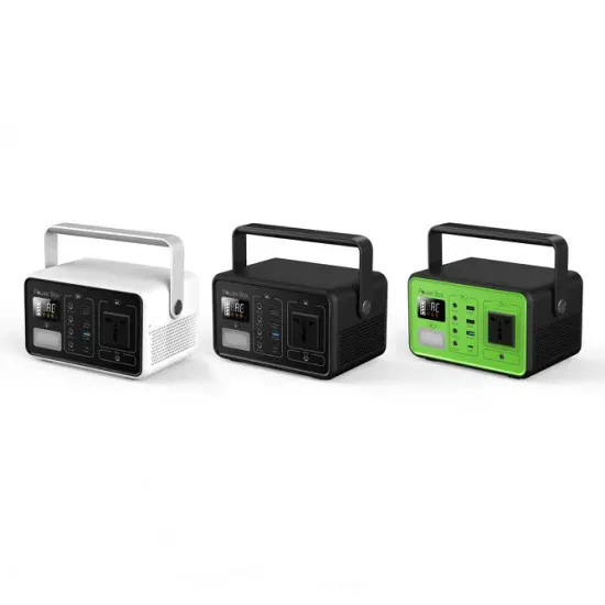
The global commercial and industrial solar energy storage battery market is experiencing unprecedented growth, with demand increasing by over 400% in the past three years. Large-scale battery storage solutions now account for approximately 45% of all new commercial solar installations worldwide. North America leads with 42% market share, driven by corporate sustainability goals and federal investment tax credits that reduce total system costs by 30-35%. Europe follows with 35% market share, where standardized industrial storage designs have cut installation timelines by 60% compared to custom solutions. Asia-Pacific represents the fastest-growing region at 50% CAGR, with manufacturing innovations reducing system prices by 20% annually. Emerging markets are adopting commercial storage for peak shaving and energy cost reduction, with typical payback periods of 3-6 years. Modern industrial installations now feature integrated systems with 50kWh to multi-megawatt capacity at costs below $500/kWh for complete energy solutions.
Technological advancements are dramatically improving solar energy storage battery performance while reducing costs for commercial applications. Next-generation battery management systems maintain optimal performance with 50% less energy loss, extending battery lifespan to 20+ years. Standardized plug-and-play designs have reduced installation costs from $1,000/kW to $550/kW since 2022. Smart integration features now allow industrial systems to operate as virtual power plants, increasing business savings by 40% through time-of-use optimization and grid services. Safety innovations including multi-stage protection and thermal management systems have reduced insurance premiums by 30% for commercial storage installations. New modular designs enable capacity expansion through simple battery additions at just $450/kWh for incremental storage. These innovations have improved ROI significantly, with commercial projects typically achieving payback in 4-7 years depending on local electricity rates and incentive programs. Recent pricing trends show standard industrial systems (50-100kWh) starting at $25,000 and premium systems (200-500kWh) from $100,000, with flexible financing options available for businesses.